
Converted wave seismic surveys
Due to different P and S velocities, the raypath geometry of the two types of reflected waves is different.
When dealing with converted waves, the reflection point is known as the conversion point, since is where the P energy is converted into shear energy.
This reflection point is no longer at the midpoint between the source and receiver (x/2). The true reflection point is depth dependent. This means that traditional procesing techniques must be modified for this new geometry.
In converted wave acquisition, the source is usually a conventional seismic energy source, either explosive or vibroseis.
Three component geophones
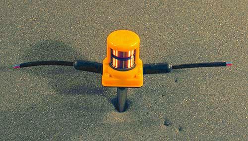
Traditional seismic exploration uses single-component geophones. These phones only record the vertical component of the ground motion, which is dominated by P-wave energy.
The geophone on the top-right has had the plastic protective case and the metal case of the coil cut away, so the the windings of the magnetic coil inside are visible.
To record S-wave energy requires a three-component geophone,which records the full three-dimensional ground motion.
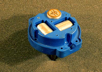
The geophone on the center-right is shown with the top part of the case removed so that the coils are visible. The three coils are oriented at 90 degrees to each other (orthoganal configuration), thus recording ground motion along the three primary axes. These are refered to as the vertical, inline and crossline components.
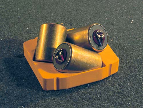
Shown on the bottom-right is an alternate coil configuration for three-component geophones know as the Gal'perin configuration. The three coils are oriented at 54.7 degrees to the vertical; this allows identical coils to be used, instead of coils optimized for vertical or horizontal orientation.
Raw vertical and radial shot records
| 4.5 Hz vertical component shot record
| 
|
| 4.5 Hz radial component shot record
| 
|
From Margrave, G.F, Estimates of the signal band of the Blackfoot broad-band data, CREWES Research Report Vol. 7, 1995, ch39
Converted wave survey design
Above are shown P-P and P-S foldmaps from the Blackfoot 3D-3C survey, shot in the summer of 1996.
The Foldmaps show the number of times that a given area of the subsurface will be the reflection in a seismic survey. High fold will minimize the noise present in the data, and an even fold distribution minimizes the trace-to-trace variation and the normalization required to correct amplitude variations when the data is stacked.
Since the P-S conversion point varies with depth, the P-S foldmap also varies with depth.
The subsurface fold is determined by the geometry of the shots and receivers on the surface.
From Lawton, et. al., Design review of Blackfoot 3C-3D seismic program, CREWES Research Report Vol. 8, 1996